Establishing Flow Bumper Supported Basal Flow in Incubator & Best Practices
Introduction
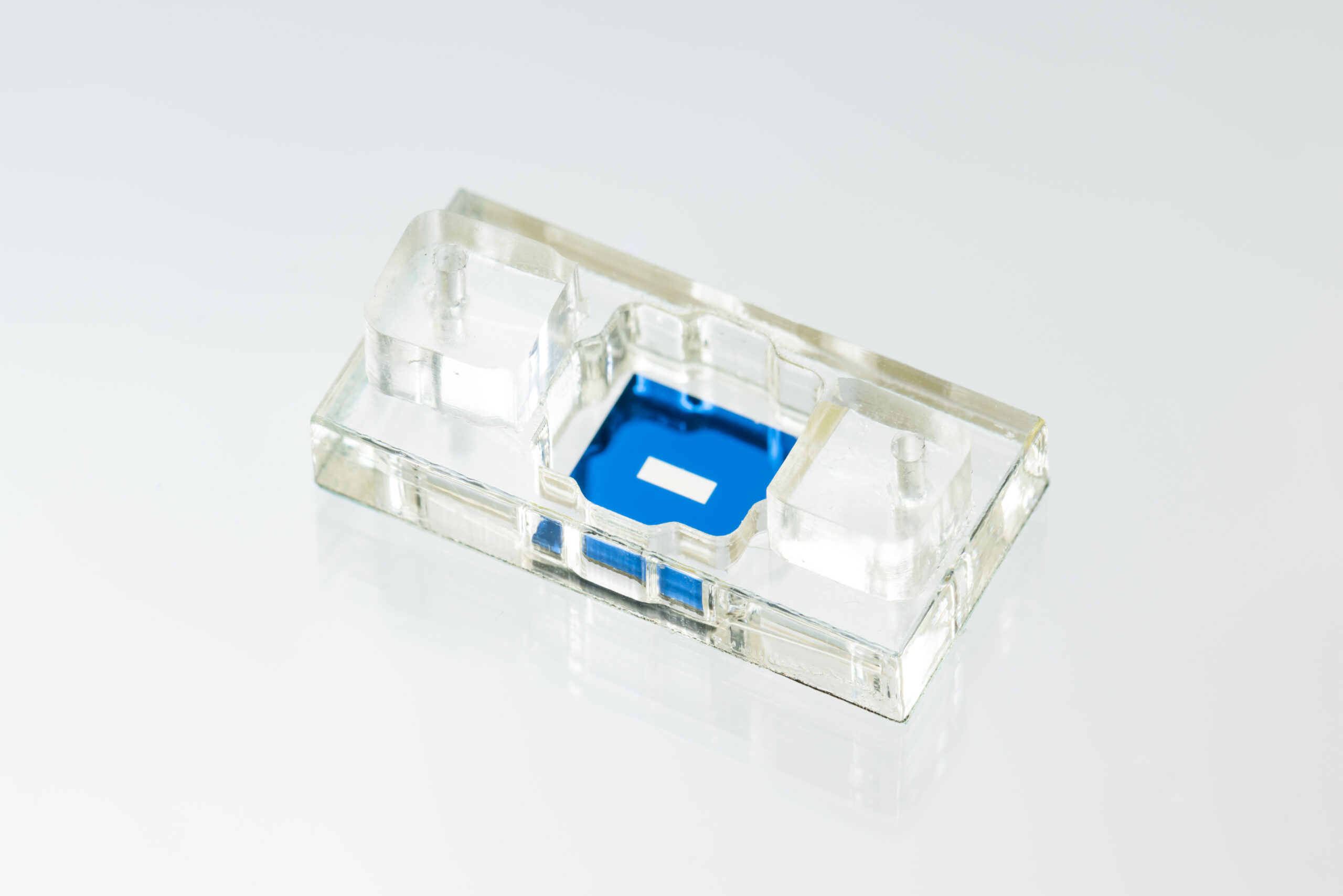
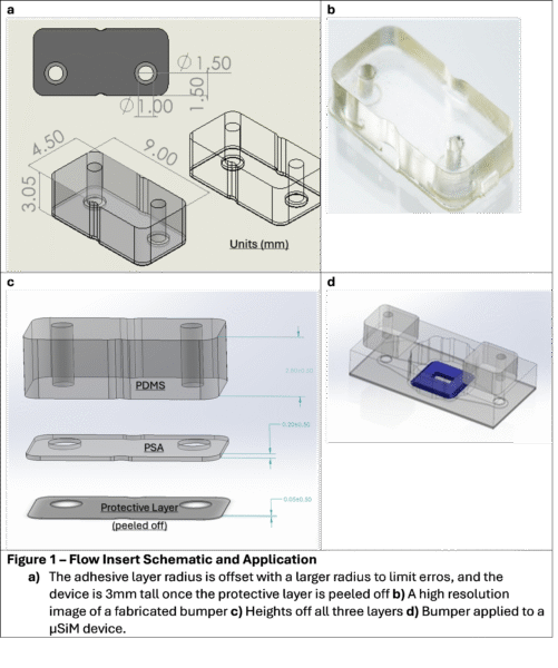
The modular µSiM device allows for active flow and continuous monitoring, but the acrylic-needle interface may experience incomplete sealing over longitudinal studies, so the need for an adaptable and intuitive approach for leak-free bottom-channel flow arose. Jordan Jones, Ahmet Gurcan, and Kevin Ling adapted the flow inserts to develop Flow Bumpers, a PDMS-adhesive component to be added onto the inlets of the devices and securely hold the cannulas in place to prevent leakage during bottom channel flow. We have recently validated the flow bumpers and developed some best practices (at end of post).
The model composition is similar to the flow insert for the well, shaped for channel support. PDMS is known for its gas permeability, biocompatibility, and easy fluidic integration, so it makes sense to stick with these materials. Further, flow bumpers are manufactured in a 25-module array mold, enabling high scalability.
The bumpers are designed to be used for devices with either single-channel flow or parallel multi-channel flow. There is a groove in the middle that can be used as a guide for slicing the bumper in half for single-channel flow. The adhesive surface area of the bumpers is high in order to increase bond strength and stability. The following validation experiments were performed for single-channel flow.
Validation Tests
I – Sterilization Techniques
Sterilization is a key step for usage of flow bumpers for cell culture experiments. We first tried to flow 70% v/v ethanol through assembled devices with freshly adhered flow bumpers. However, we realized that this leads to immediate bond failure due to ethanol exposure. We further tested this by liberally spraying ethanol directly on the bumpers or by gently spraying and wiping the top. We found that allowing the assembled device to sit for 3 hours or 3 days led to better adhesive properties, but ethanol still weakened both. We adjusted our protocol to sterilize the module by spraying a kimwipe with ethanol then gently wiping the top surface rather than spraying the bumpers directly. This is followed by a brief (5-10 minutes) UV exposure. Using this method, we confirmed stronger, longer-lasting adhesion and leak-free performance.
I – Setup
For this test, we utilized a peristaltic pump (Longerpump BQ501J and a two-reservoir circulating flow module. Before adding any devices, we sterilized the flow module with ethanol for two hours, flushed the circuit with water for an hour, and finally flushed with DPBS for an hour. The device was attached to the circuit, and the reservoirs were filled with about 20 mL of DPBS. The pump was set to a flow rate outside of the incubator, then the power cord was sprayed with ethanol and passed through the back of the incubator. A large petri dish (Falcon, 150 mm) had holes cut in it to hold the tubing to the device steady, and the circuit was contained on a large glass tray which could be easily transferred between the incubator and biosafety cabinet for maintenance.

III – Leaking Membrane
After 1 week of flow we had no failure from the flow bumpers but observed continual leaking – a slow accumulation of fluid in the well that ultimately spilled over. We at first contributed this towards potential membrane imperfections so we switched to use newer membranes and observed the same issue. We hypothesize that “wetting” the membrane is what allows for basal to apical transport, aligning with observations from Karl Smith (1) regarding the force needed to overcome the LaPlace pressure at an air-water interface compared a water-water interface. The Laplace pressure can be determined from the young-laplace equation given as:
![]() where γ is the surface tension of the liquid, ΔP is the pressure difference across the membrane, and R’s represent the principal radii of curvature of the interface. Smaller pores increase pressure, but the angle of contact of the fluid-air interface influenced by wetting the top of the membrane is the driving factor for these experiments – a smaller contact angle decreases the surface tension and reduces the curvature, rendering the laplace pressure close to 0 when fully wetted.
where γ is the surface tension of the liquid, ΔP is the pressure difference across the membrane, and R’s represent the principal radii of curvature of the interface. Smaller pores increase pressure, but the angle of contact of the fluid-air interface influenced by wetting the top of the membrane is the driving factor for these experiments – a smaller contact angle decreases the surface tension and reduces the curvature, rendering the laplace pressure close to 0 when fully wetted.
Even under the fastest flow rate possible of the peristaltic pump over 30 minutes we observed no leaking in this interface. As noted above, we had a high flow rate when the device leaked but also observed this after lowering to 96 uL/min. We hypothesized that adding an ARPE-19 cell barrier on the apical side of the membrane would negate this basal to apical permeability.

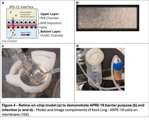
APPE-19 barrier
We seeded ARPE-19 cells on top of the nanomembranes and allowed them to form tight barriers then started flow on day 6. After 48 hours of basal flow at 96 uL/min, 250 microliters of media leaked out of the device. Most of the initial media was still contained within the circuit. Over the next several days, we would pull around 100 uL off the sides of the device to re-level the bubble to be contained in the 100 uL well. Qualitatively, we observed substantially less leakage than membranes without cell seeding, but additional experiments are needed before we can make conclusions.
The apical side of the membrane, though covered with a cell layer, remained open to atmosphere. We hypothesize that a flow insert, which would drastically reduce the exposed surface area, would greatly reduce all leakage. Determining the pressure difference of the membrane and balance in transport across it is of critical importance as we determine how to expand the µSiM to various models of physiological and diseased states for several systems.
We did not get the opportunity to perform permeability testing due to infection on day 6 of flow. This apical layer is adapted from Kevin’s experimental setup, referenced below.
Materials and Methods
We used component 1 v10, batch 25 for the main acrylic body and component 2 v10 batch 40 for the bottom. Flow pumper SO#: AL24093 from 12/30/24
For barrier testing we used comp 1 v10 batch 12 and comp 2 v10 batch 35
Membrane: Initially lot 1380LL, NPSN 100-IL, then lot 240803-14, NPSN100C-ILZ.0 to confirm observations
0.55” cannulas in the flow module
Masterflex 1/16″ ID x 1/8″ OD Tubing (This is the thicker tubing, which is the more critical component of driving flow rate)
We used a soldering iron to two put holes that match our tubing diameter about 1/3 of the circumference apart to allow tubing to pass through the sides while still containing the top to prevent infection. The goal is to have the tubing fit snugly so that they remain in their rotational position and don’t apply torque on the device. A proper holder will also help with this issue.
Previous device holders had functional use but large clearances that allowed for them to fall out. We used 0.2 mm clearance, the general width of a FDM 3D printer extrusion. This design worked out well and allowed the device to “click” into place and be secure with the bottom and top completely accessible and visible. I extended the bottom to allow for an improved viewing window, as well. I have a format I designed to work with 96 well plates, so this tolerance can be extruded from that face to allow devices in parallel. All files are contained in box.

Summary
PDMS flow bumpers were able to maintain high flow rates for a week in an incubator – the point of failure was the membrane leakage and I would expect that they last through a two week experiment as well so long as they are kept dry in the early bonding phase and not exposed to excess EtOH. They seem to be a great addition to the µSiM portfolio.
The point of failure was seldom the PSA to the acrylic device and more often the PDMS to the adhesive, so our handling of pressure and time wouldn’t improve upon this.
Nanomembranes that are wet on both sides will slowly leak without back pressure.
Chip holders and reservoir modules can keep our systems secure and particularly reduce tubing tension to allow stability of experiments, even when moving them.
Suggestion for Protocol:
Note – only open components inside a fume hood – once exposed to unsterile conditions you cannot assume sterility.
- Liberally Spray all needed components (in packaging) and tools with ethanol and transfer into fume hood before opening packaging
- Take the device components you need out of their packaging – you may soak or liberally spray with ethanol.
- Leave the protective layers ON the components while soaking – ethanol may disrupt the adhesive
- Membranes do not receive any ethanol treatment.
- Spray and UV-treat flow bumpers for 5 minutes. While they are being treated you may assemble devices
- Assemble Devices:
- Peel off the protective layers from component 1 (body) and carefully seat the membrane into the jig. You can apply in the packaged orientation for trench-up work or flip it around for trench-down work.
- Place component 1 onto the membrane and close the jig, applying ample pressure for at least a minute – PSA bond strength increases over time and pressure
- Peel off the protective layers of component 2 place it in the jig, and then take the component 1 piece and place it on top. Repeat the pressure.
- If needed, slice the flow bumper in half. Peel off the bottom layer. Put a cannula through the channel and use that to ensure it is aligned with the device. Use forceps to apply pressure along the bumper, then firmly hold them in place while wiggling the needle out.
- The bumper will likely come off if you pull the needle out without holding down with forceps. You can improve these odds by allowing the PSA to strengthen for a half hour, or even overnight if needed.
- Your device is now assembled. We suggest priming with pure water rather than ethanol to avoid disruption of bonds.
Future Work
We can utilize a sealed-off top well to negate the pressure difference and run a two-week cell-free experiment with media to show no leaking through the flow bumpers. Sterilizable glue will allow everything to be autoclavable (mostly speaking to the flow module here)
We want to determine why the smaller reservoir fills up faster and prevent this – perhaps adjusting tubing diameters and heights can help. Some UV-functionalized adhesive could perhaps have stronger bonds and be simultaneously sterilizable.
References
- Smith, Karl J P. “Understanding Sieving and Clogging in Ultrathin Membrane Filtration,” 2017.