Electron Beam Evaporation, RIT vs UR
The CHA e-beam evaporator in RIT had been used traditionally for the deposition of metal on the pnc-Si membranes. The most important factor for metal deposition on the membranes is that the nanoholes must not be blocked. So the metal deposited needs to be smooth and continuous. Ag or Au does not adhere onto Si surface, so a layer of Ti is first deposited on top of Si layer to act as the adhesion layer between Si and the metal.
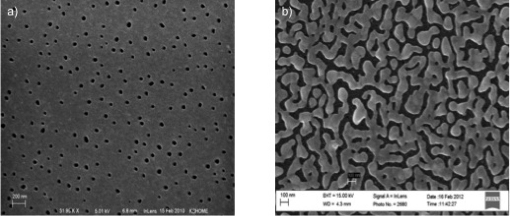
The following are the SEM images of the metallized membranes. The metal layers were deposited in RIT using the CHA ebeam evaporator. The membranes were 30 nm in thickness, the metal was deposited on both sides. Each side has 3 nm of Ti and 13 nm of Au. Figure 1a) shows the SEM image where the metal is continuous and the holes are not blocked. Figure 2a) shows the SEM image of the metallized membrane where the Ti layer was not adequately deposited. These figures shows that SEM is a convenient tool in characterizing the metallized membranes.
To quantify the surface roughness, an AFM image of the metallized membrane (deposited using the CHA- ebeam evporator) was taken using the NT-MDT AFM. The image is shown below
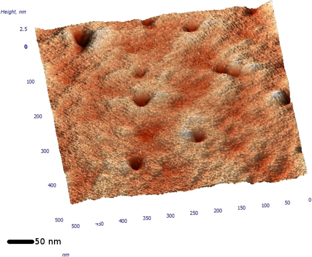
These images show that deposition using the CHA ebeam evaporator gives a smooth metal film over the membranes. A single deposition on the CHA ebeam needed at the least 4 hours of pumpdown to reach pressures of ~1e-6 Torr. Most of the depositions were done after an overnight pumpdown of the chamber.
The Kurt J. Lesker, PVD-75 is a tool that is currently in the URNano facility. The pumpdown times is significantly lower than the CHA-ebeam evaporator. With the chamber reaching 1e-6 Torr pressure in an hour or less. However this chamber is small compared to the other, so it is difficult to use angle deposition techniques on samples here.
3 nm of Ti and 15 nm of Au was deposited on TEM grid pnc-Si membrane. The SEM was taken on the interface between freestanding membrane and the substrate. The image is shown below


The images show that the metal films over the freestanding membrane appear to be cracked. This maybe because of vibrations of the membrane. On the substrate the metal film appears to be continuous and the nanoholes are open.
This is a problem for deposition using the PVD-75, not seen in the CHA ebeam evaporator. It is suspected that the vibrations are intense because the membranes are perpendicular to the direction of the evaporating metals. Keeping the membranes at an angle may lessen the mechanical vibrations of the membranes during deposition.