AFM studies on HUVECs in Aline Devices
Introduction
Previous work was done on determining physical properties of the glycocalyx of endothelial cells, this was performed on glass inserts using the Asylum AFM. We wanted to continue this testing using the Aline uSim devices in order to determine any significant differences between our devices and the glass bottom flow system developed in the previous studies.
See references:
1) https://doi.org/10.1016/j.bpj.2020.02.010
2) https://doi.org/10.1152/ajpcell.00259.2020
Initial attempts
It took a few weeks to get the AFM tests up and running, there was a little experience on the instrument, but mostly rusty. It became apparent readily that the only possible way to perform these experiments was in the bottom channel of the device, while having the chip trench side up. The AFM cantilever will not make contact with the membrane through the well, nor is it long enough to reach the membrane when seated trench side down.
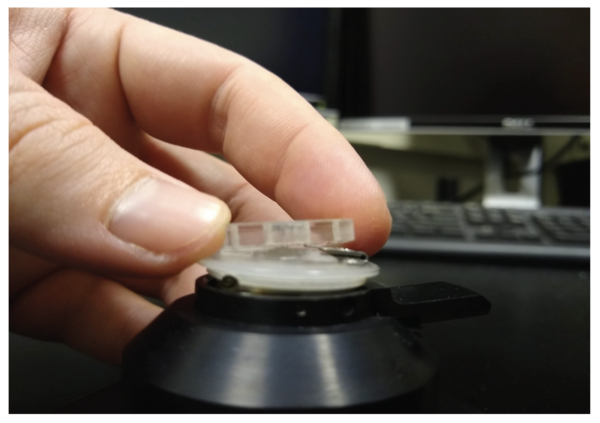
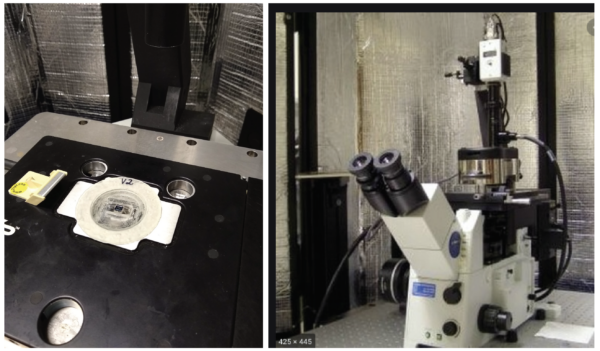
We have seeded cells in the bottom channel of devices before without issue, so the second problem we began to encounter is both maintaining an appropriate water/media level in the AFM to maintain the cells while performing the force experiments under the AFM tip, this was coupled with the issue of getting the chip in focus in order to visualize the membrane and cell layer via phase contrast imaging. On the provided glass inserts the chip sat outside of the working distance of the microscope objective. To remedy these issues we turned to prototyping our own device holders so the chips could be reached by the cantilever tip, focused on by the microscope, maintain a significant media reservoir, as well as keep the device securely in place so we would not get additional vibration in the tests.
Using the FormLabs 3D printer we prototyped 2 versions of the device holder shown below. Version one came with drawbacks, the design was developed with precision in mind and did not account for variability in the printer as well as chips. Version 2 has worked much better and is the current go-to system, it is not without flaws, so a version 3 is being prototyped now.

Current issues with the version 2 holder have made it difficult to secure the device in to the imaging space, and when the chip does fit into the space, we have seen on more than one occasion that pressure builds up in the well and can burst the membrane since the fluid gets trapped in the well and has nowhere to escape except through the membrane. We are close to a system that works easily and repeatedly. Our version 2 does work, it is just not a simplified design for ease of use.
Results
We have been able to follow the experimental procedure from the previous studies. We have aligned our cantilever to contact the cell in near, but not touching, the nucleus. This is to prevent the nucleic thickness and stiffness to disrupt our indentation of the glycocalyx. The procedure continues on for us to indent into the cell until we reach a threshold force measurement of 5nN. The cantilever tip is then retracted, and the cell is allowed to recover for 10 seconds before this indentation is taken again. This process is performed 10 times on a single cell and then a new cell is chosen.
We have obtained multiple series of the force and indentation curves as shown in the figures, we have also been able to capture the position of the cantilever with respect to the cell using phase contrast. The raw data is shown here as deflection v. z-postion of the cantilever, these data sets are able to be extracted and will be processed further in Matlab using the same processes described in the previous studies done on the glass bottom flow chambers.
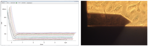

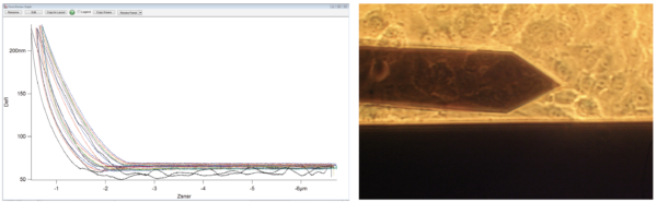
Knowing the tip location and location relative to the membrane window could be invaluable information, which this set up allows for us to capture both aspects. We’ve noticed that when we are either too close to the nucleus, or that a nucleus is sitting underneath the cantilever close to the tip, that we capture these arcing indentation curves that appear predominantly in the retraction portion of the cantilever journey. We can use this to help fine tune our aim on future samples, and ensure we are not finding ourselves in drastically different portions of the cell for each indentation experiment. Secondly, the location in regards to the membrane window could provide important as the flexibility of the membrane can change over the entirety of the window, and this could impact these indentation and force curves if the center of the membrane is significantly more flexible than the edges.
Another issue that we have approached is that Aline holder we prototyped does not guarantee a perfectly flat seating of the Aline device underneath the AFM head. This is only an issue in that frequently it has restricted up in the area that can be tested without significant shifting of the AFM headpiece. Since the cells have been confluent for the tests above, there was no issue finding 10 cells to test, however if we needed to test edge cells and middle-of-window cells things could get complicated.
Future work
We are redesigning our Aline device holder to help prevent window blow-out and to more easily prevent the device from moving during these indentation studies, and prevent the whole device from floating. But more importantly we are working on testing and performing these experiments on cells that have been grown under flow conditions, as well as treated with an enzyme that is meant to disrupt the glycocalyx in order to obtain controls for these experiments. The end goal of this work would be to perform these exact same studies on the same cell lines being produced by Molly and on our Aline devices.
