Blood Cell Separation Using Microslit Chips
Over the summer, I have been working on a project with Rick Waugh that focuses on separating white blood cells from red blood cells. The goal is to be able to take a lancet droplet of whole blood and perform an analysis on this blood, whether it be for white blood cell phenotyping or exosome isolation, a preliminary step in either of these analyses would be blood cell separation. Due to the current chip constraints (their dimensions are not right for full separation of the cells and plasma), the white blood cells were the targets in our study.
The chips that I used for this experiment were the 5.4 x 5.4 mm SepCon format and were patterned with microslits instead of pores. The slits were estimated to be 1.5 microns wide and 50 microns long, but were in fact closer to 3.5 microns wide and 50 microns long, as shown in Figure 1.
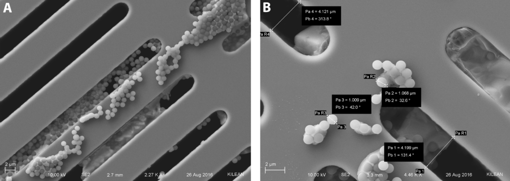
Figure 1: Microslit membranes with fluorescent microbeads for calibration.
One of the underlying principles of this rotation was to use tangential flow to perform an efficient separation of the red blood cells from the white blood cells. Tangential flow will prevent fouling of the membrane, which is very likely to occur if we were to use normal flow and whole blood. Additionally, tangential flow is more amenable to smaller volumes of blood, as it would be very difficult to centrifuge tens of microliters of blood. The applications of this technique also reach beyond red and white blood cell separations. The original motivation of this rotation was to be able to separate immature red blood cells from mature red blood cells (the difference being the absence of a nucleus), which should be possible with smaller slits. Additionally, this technique can be used for the separation of cells from blood plasma, which can then either be dialyzed or used for exosome capture. Whatever the application, this project has a much wider range of applications than I think was originally desired.
In the experiment that I did over the summer, used a very similar format to the devices that I use for exosome separations, but with a few small modifications (Figure 2). The two most notable changes were the addition of a sample reservoir and a second pump. These changes actually significantly impact the performance of this particular device.

Figure 2: Blood fractionation device setup. Design changes include a clampable system with imaging ports for optical imaging, a fluid reservoir to combat gravity effects on settling, and two pumps for a constant transmembrane pressure.
To begin with, I incorporated the reservoir due to the effects of gravity. In the first iteration of the device, I loaded a syringe with my sample and pumped it across the top of the membrane, as I normally would. However, due to the low flow rates and the length of time that I ran experiments for, cells began to settle in the tubing and thus the sample didn’t have a chance to interact with the membrane. completely. Therefore, it was necessary to switch the flow scheme and draw the sample across the surface of the membrane from a fluid reservoir that remained vertical and compensated for cell settling by allowing the cells to settle in the direction of flow.
The addition of a second pump is actually an idea that I have been toying around with for a while. The original principle of the tangential flow was to pump the sample across the surface of the membrane and the flow would generate a transmembrane pressure that drove the exosomes into the pores and retained them there while clearing protein and junk in the plasma. However, after attempting to repeat these experiments, I noticed a lack of retention of exosomes on the membrane and I guessed that was due to a loss of transmembrane “holding force” for the exosomes. Therefore, I wondered what would happen if I incorporated two pumps into the system: one to provide the tangential flow on the top side of the membrane and one to provide a constant transmembrane pressure on the bottom side of the membrane. This led me to a model for pumping at 10 uL/min on the top of the membrane and 2 uL/min on the bottom, which would let me maintain that desired constant pressure while also providing clearance of a fouling layer on the surface of the membrane. I will post on this model and describe it in more detail later.
The whole reason for the two things that I just described is due to the initial parameters in my first experiments. When I implemented the reservoir, I pulled through the membrane, which was essentially normal flow. If I pulled from the top channel, then the residence time would be too low to allow for sufficient interaction of all the blood with the membrane. However, normal flow in the case of these microslit membranes will eventually allow for all the particles to pass through the slits, which defeats the purpose. Therefore, by implementing a two pump system, I could have the benefits of the tangential flow set up with the transmembrane pressure of the normal flow system.
All in all, this was a very successful experiment so far, with observed separation of the red blood cells from the white blood cells, as shown in Video 1:
However, there is some refinement that needs to be considered, including shrinking the size of the slits to produce more preferential separation, as well as a method for counting cells to get an estimate of efficiency. I will be tackling these in the future, as they are very important for improvement of the device. Additionally, as this would be ideal for small blood drop analysis, further experiments will be done to characterize the performance with finger-prick volumes of blood.
The rest of this post will just be a collection of images that show the characterization of the system performance by SEM.
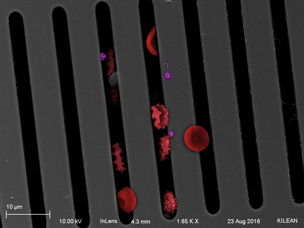
Figure 3: Red blood cells and echinocytes passing through the slits of the membrane in false color SEM.
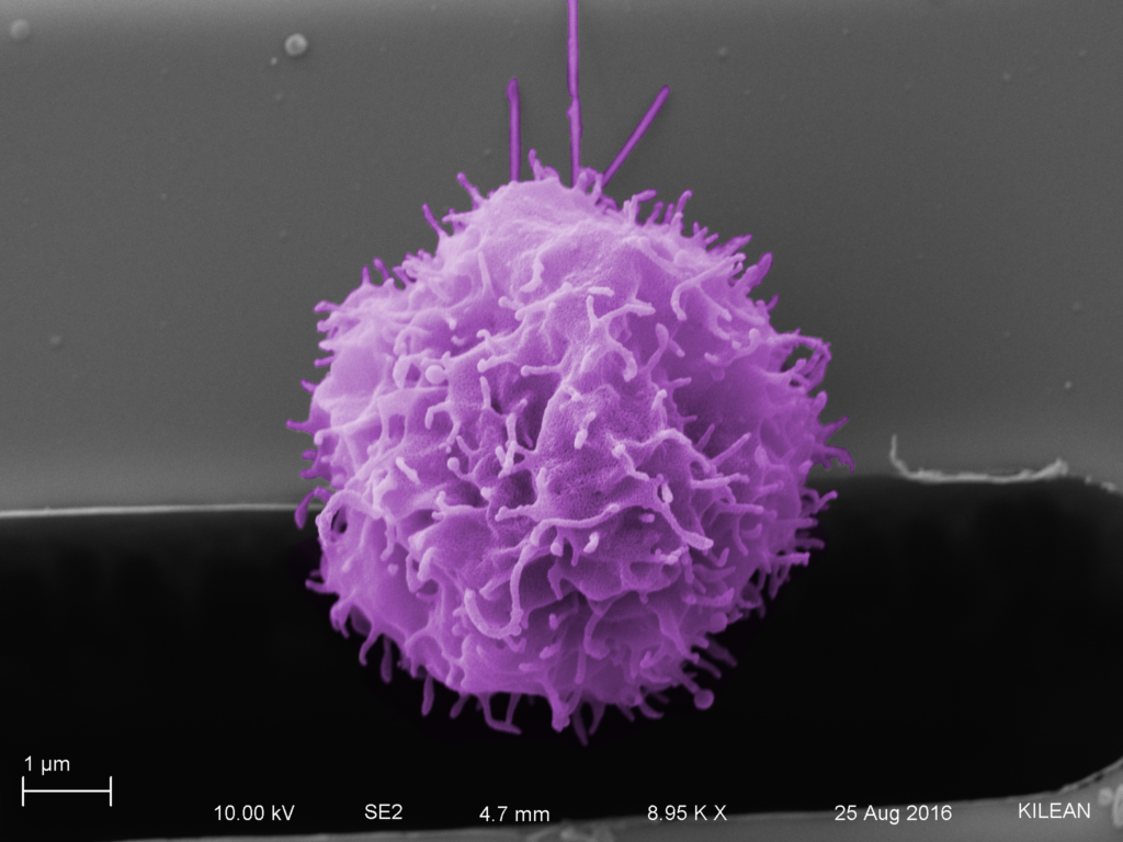
Figure 4: Tejas’s white blood cell on the microslit membrane, exhibiting the retentive properties of the membrane.
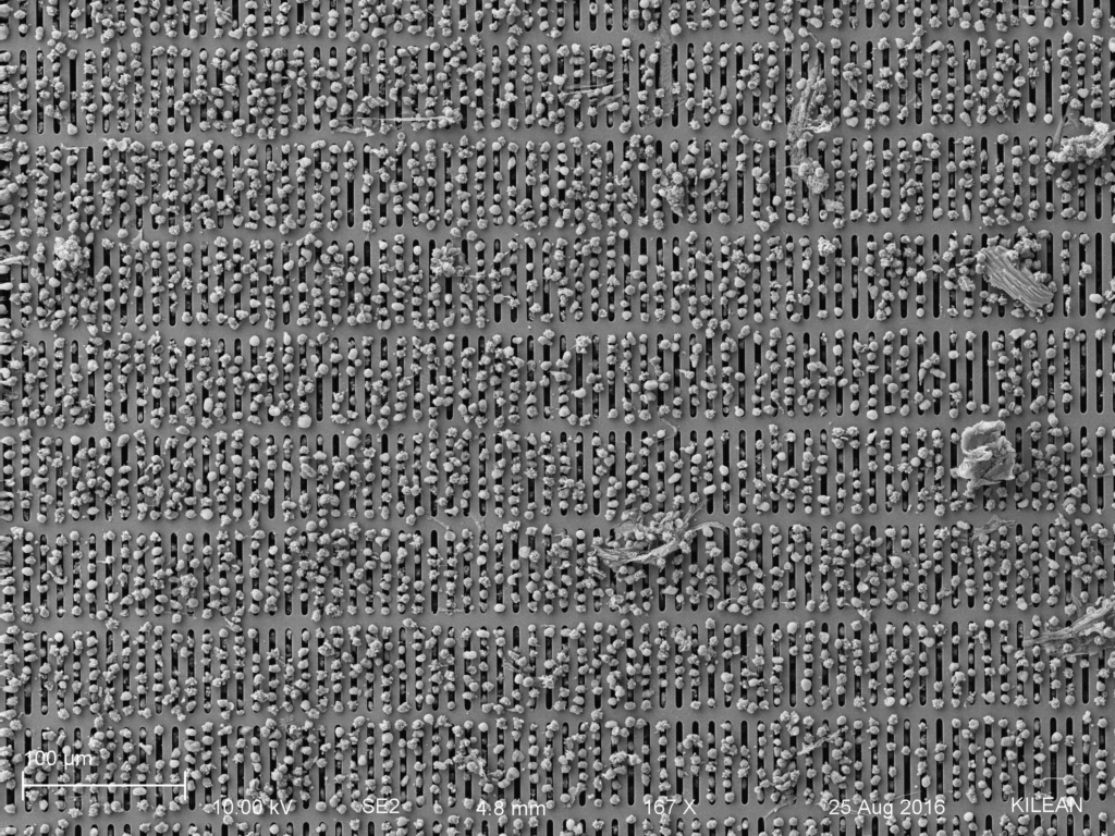
Figure 5: White blood cells retained on the top of the membrane from a 1:1 RBC to WBC mixture.
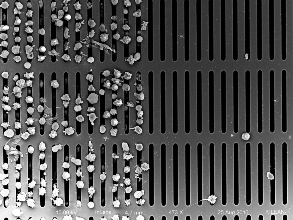
Figure 6: White blood cells retained on the membrane with a constant transmembrane pressure in the active area of the chip.

Figure 7: Despite the presence of numerous white blood cells on the slits, red blood cells appear to be able to slip around and through the slits.
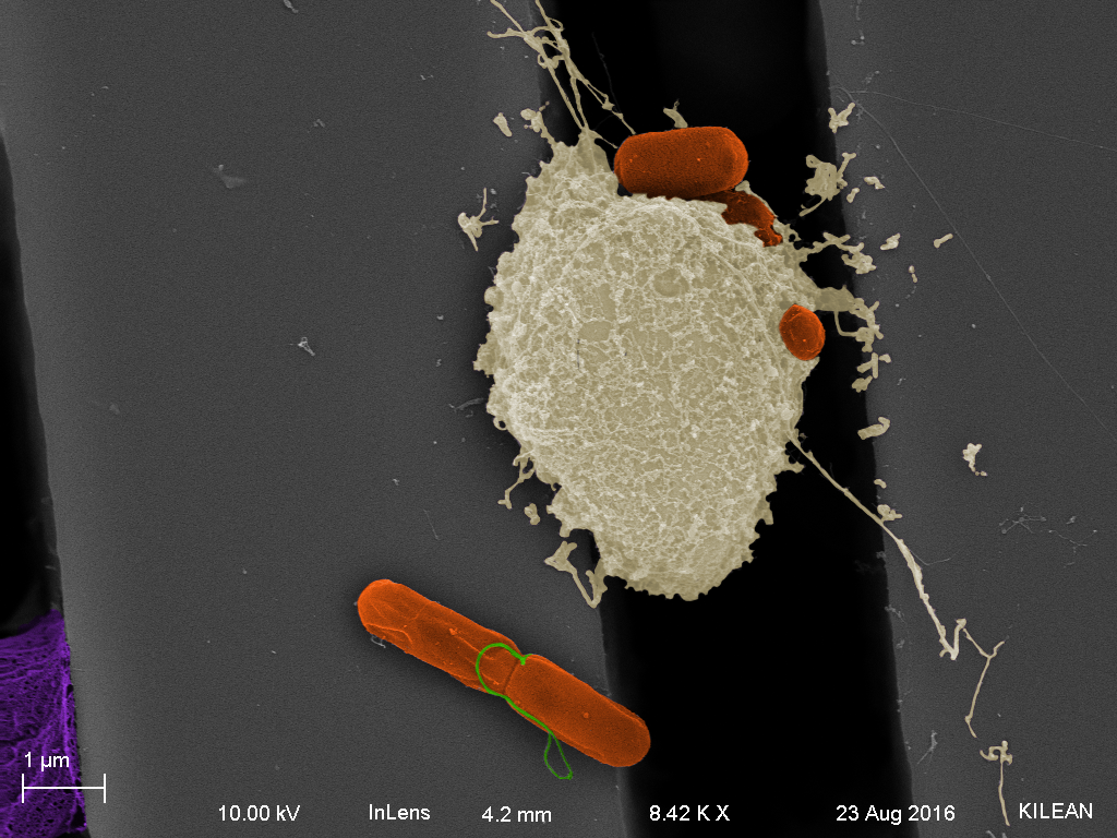
Figure 8: White blood cell engulfing a bacterium on the microslit device. The bacterium could have arisen as a contaminant in the system and the white blood cell found it and attacked it.