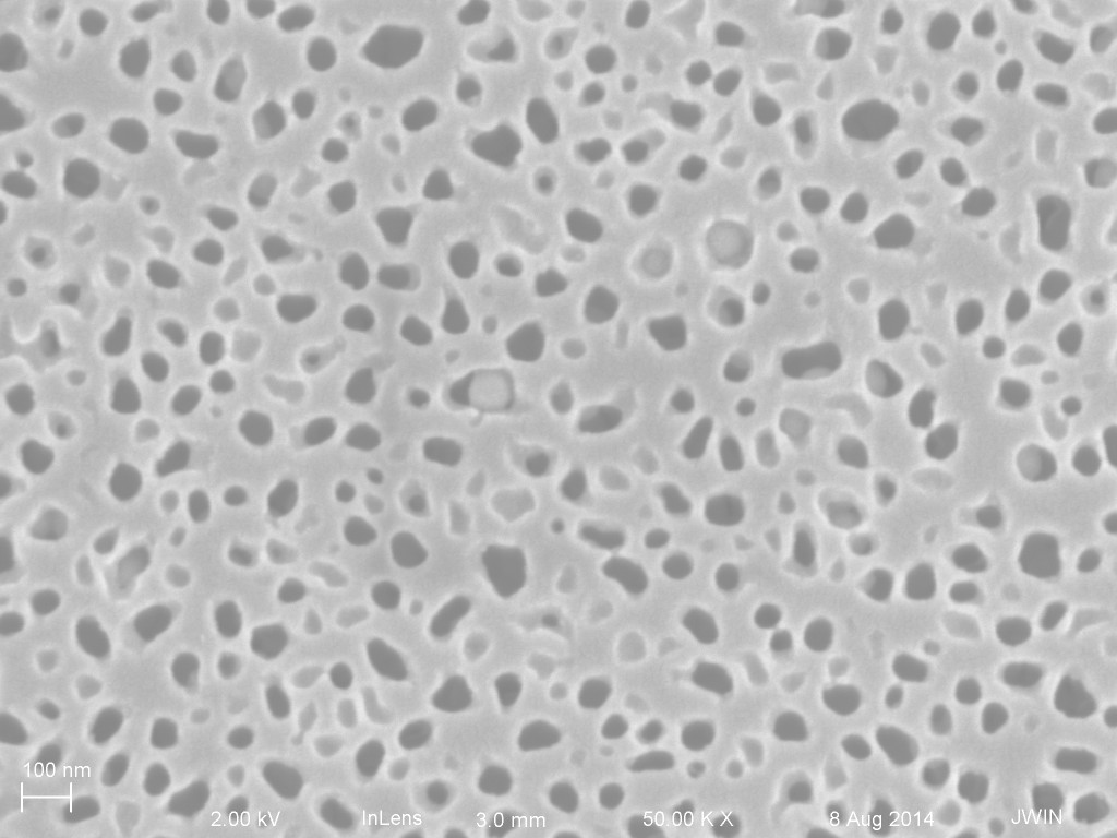
SEM analysis of NPN membranes post-filtration
As part of the ongoing study of NPN membrane filtration characteristics I used the SEM to look at membranes after they were used. Unless otherwise indicated, files with a “t” (top) indicate the chip was membrane side up. “b” stands for the bottom, or trench side. In a standard forward centrifuge setup we expect the cake layer to form on the bottom (‘b’) side in between the trenches. If we are attempting reverse centrifugation (RC) then we expect a cake later on the top (‘t’) side.
Keep in mind that these chips had in some cases sat for days or weeks between filtration and SEM inspection. They were dried by pipetting off as much liquid as possible and then being placed in a vacuum for about 15 minutes. I imagine these variables could lead to different results from sample to sample, but this is as good a starting point as any.
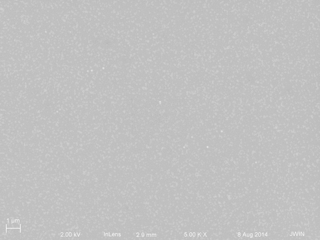
I initially tried imaging the samples as is, but charging led to pretty poor images. I later sputter Pt for 60s and had much better luck.
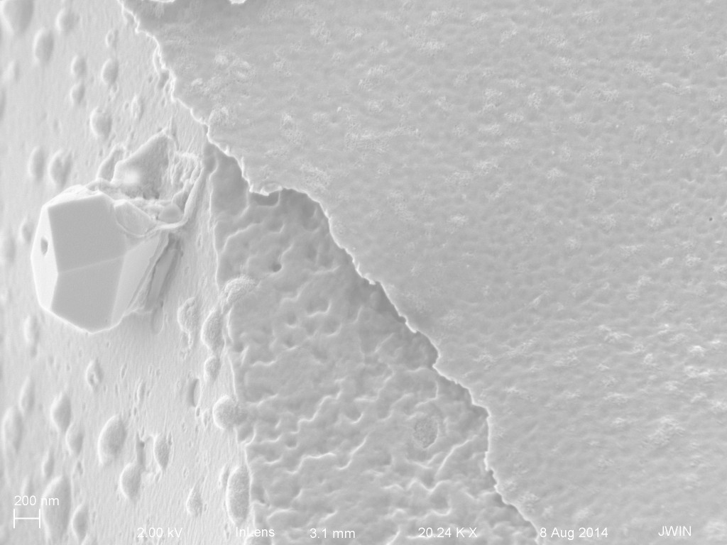
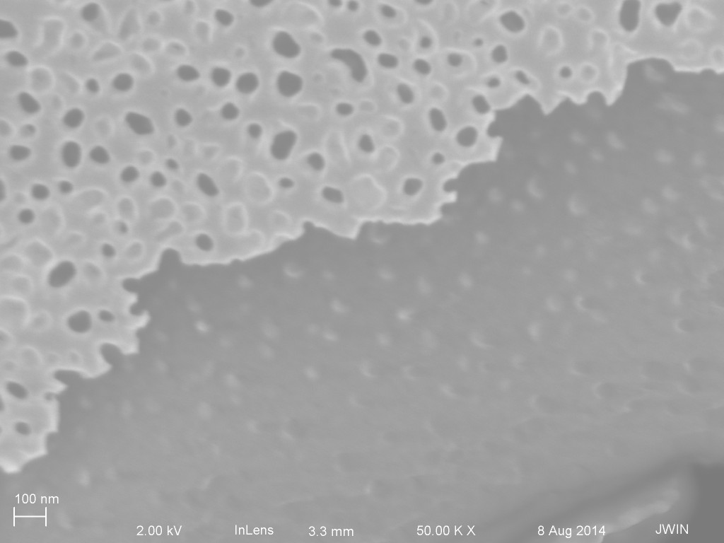
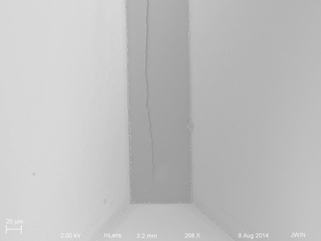
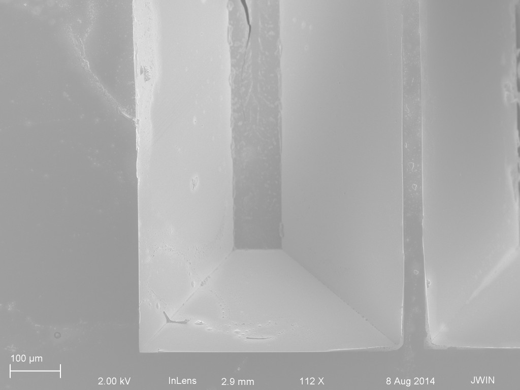
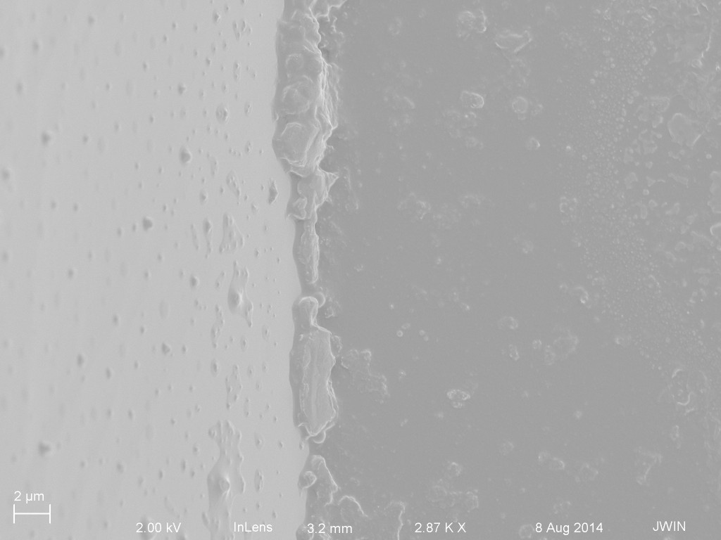
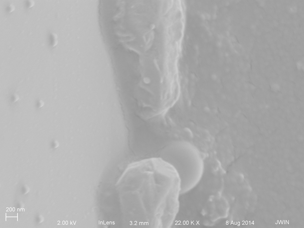
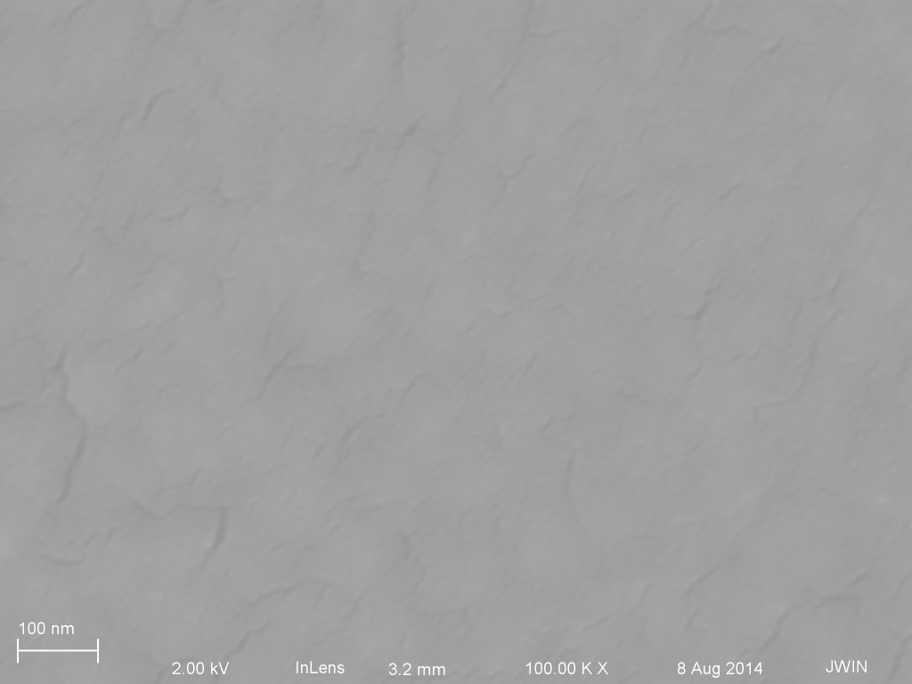
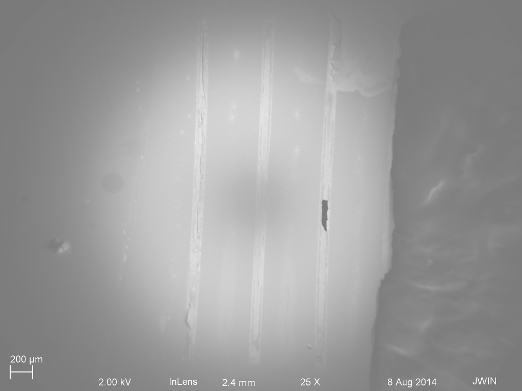
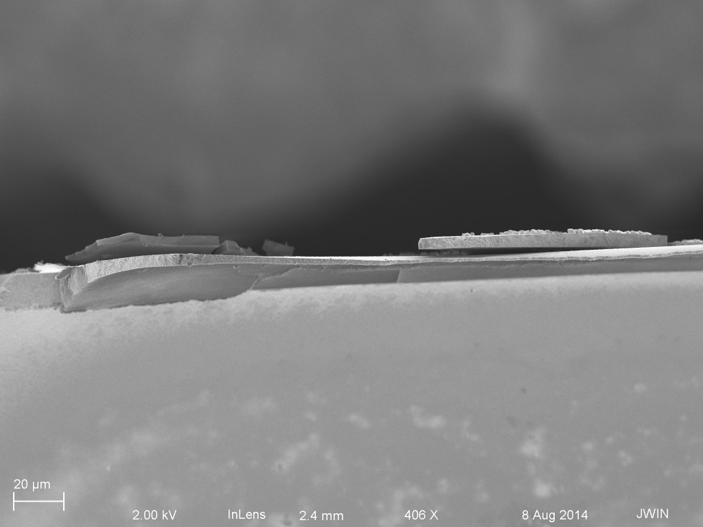
First up, 5 mg/mL IgG. I only looked at the top down view for the forward and reverse centrifugations. In both cases the top looks “clean”. Because both chips have broken membranes it is possible to see what’s behind in the trench region. Both chips have what looks like a large layer of material. This is not intuitive given that the cake layer would have formed on the front side of the forward orientation chip. Or maybe there wouldnt’ be a cake layer due to centrifugal force, but then I can’t easily explain the material in the trench area. Unless this material is there from the drying process?

And now RC:

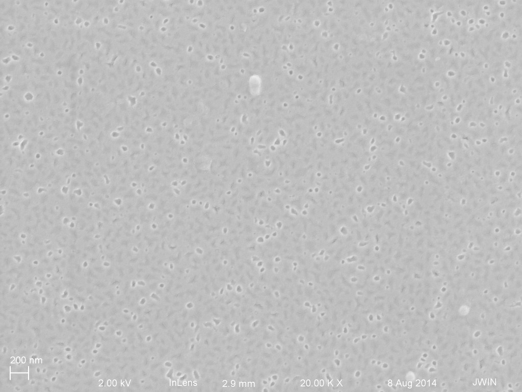
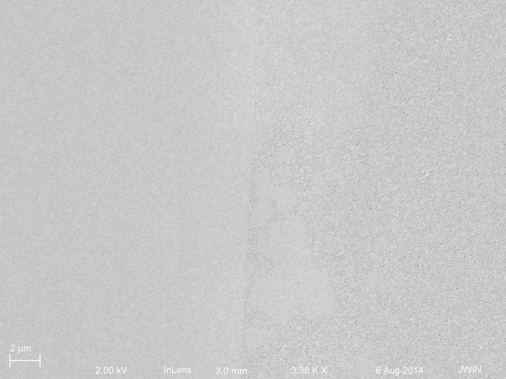
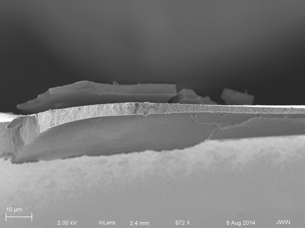
Next up I looked at FC and RC for separations of 20 nm 10^14 parts/ml and IgG 1mg/mL. On these I broke the chips so that I could look at the top and bottom surfaces at the same time. In the future I will just plan on looking at the top surface and then removing the samples from SEM and flipping them over to avoid possibly disturbing the state of the membrane. (breaking the chip usually breaks at least some membranes. And flipping the chip will probably break some of the membranes as well because they probably hit the carbon tape on the SEM holder)
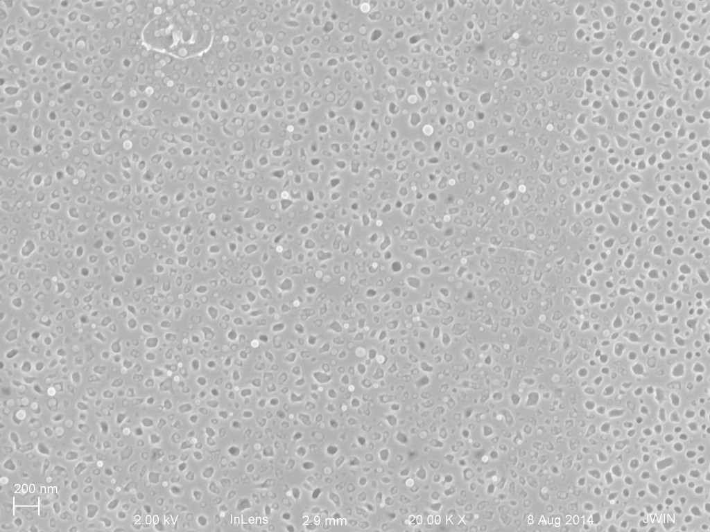

Next up are the Reverse centrifuge samples with the same NP/IgG blend:

It’s hard to differentiate between the two conditions. We may be able to claim that there is less material on the RC filter, but there isn’t much on the FC filter either.
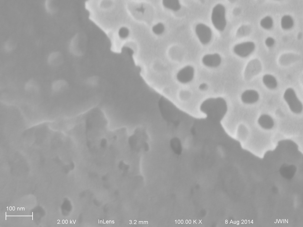
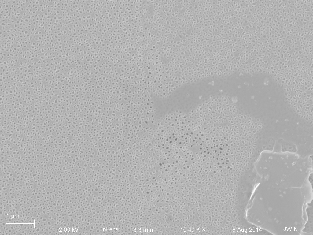
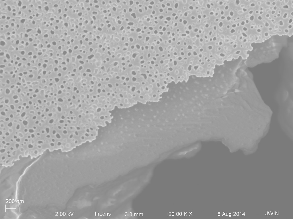
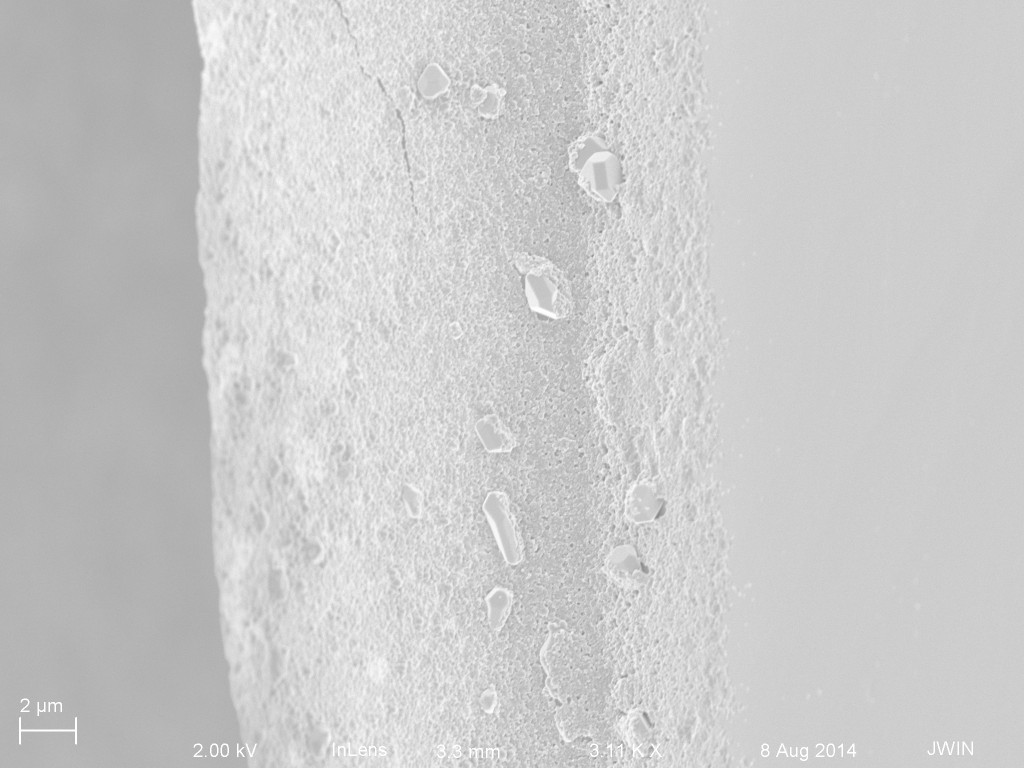
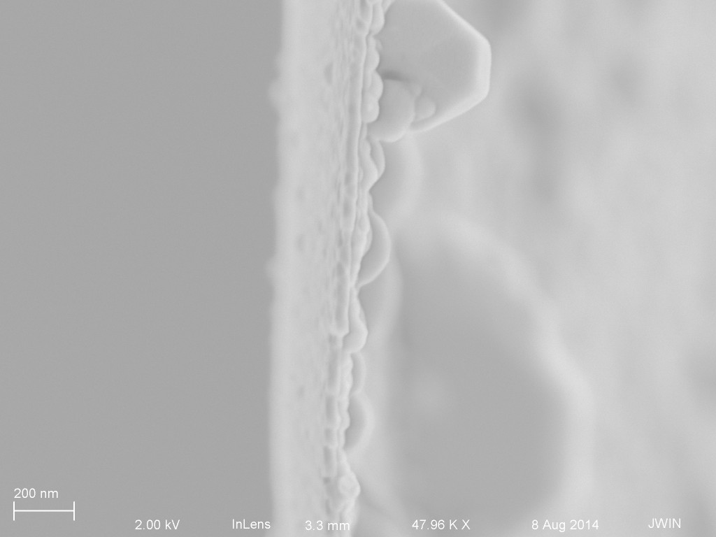
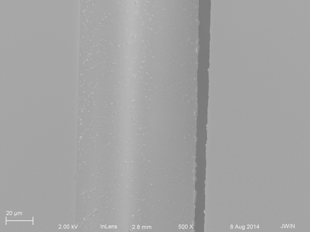
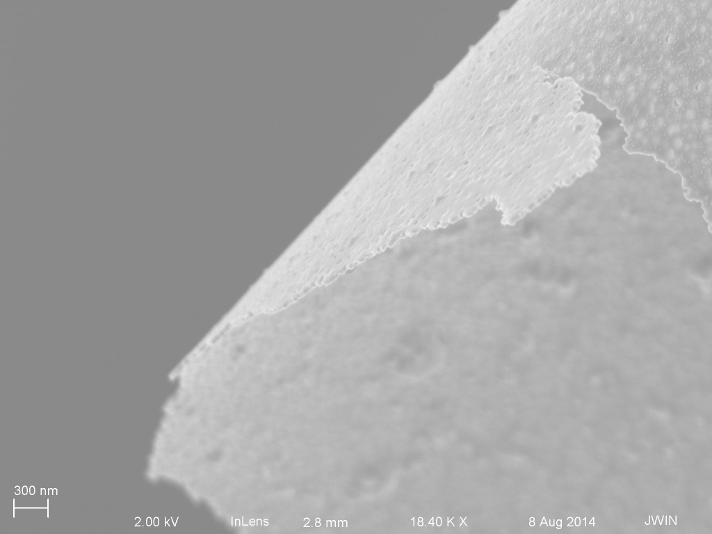
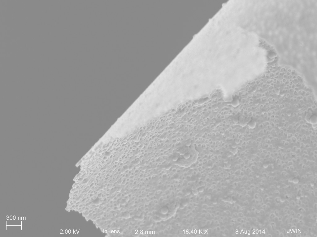
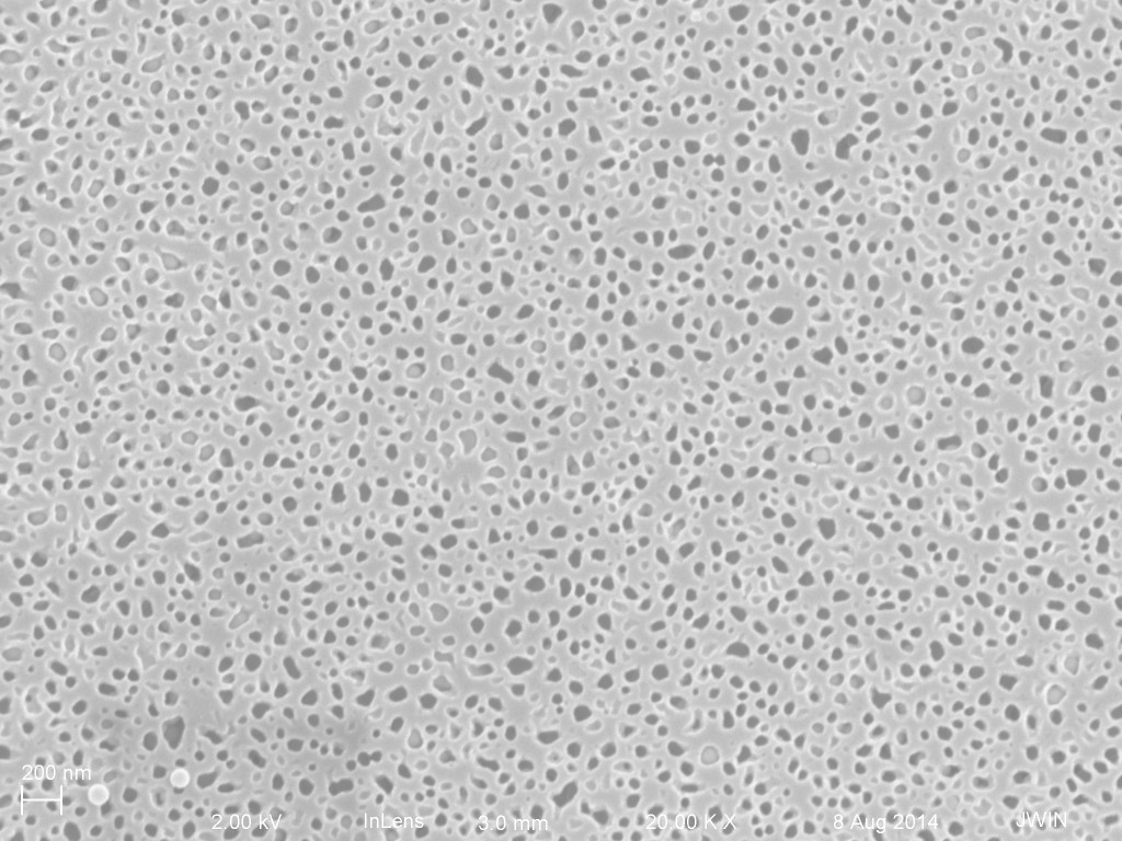
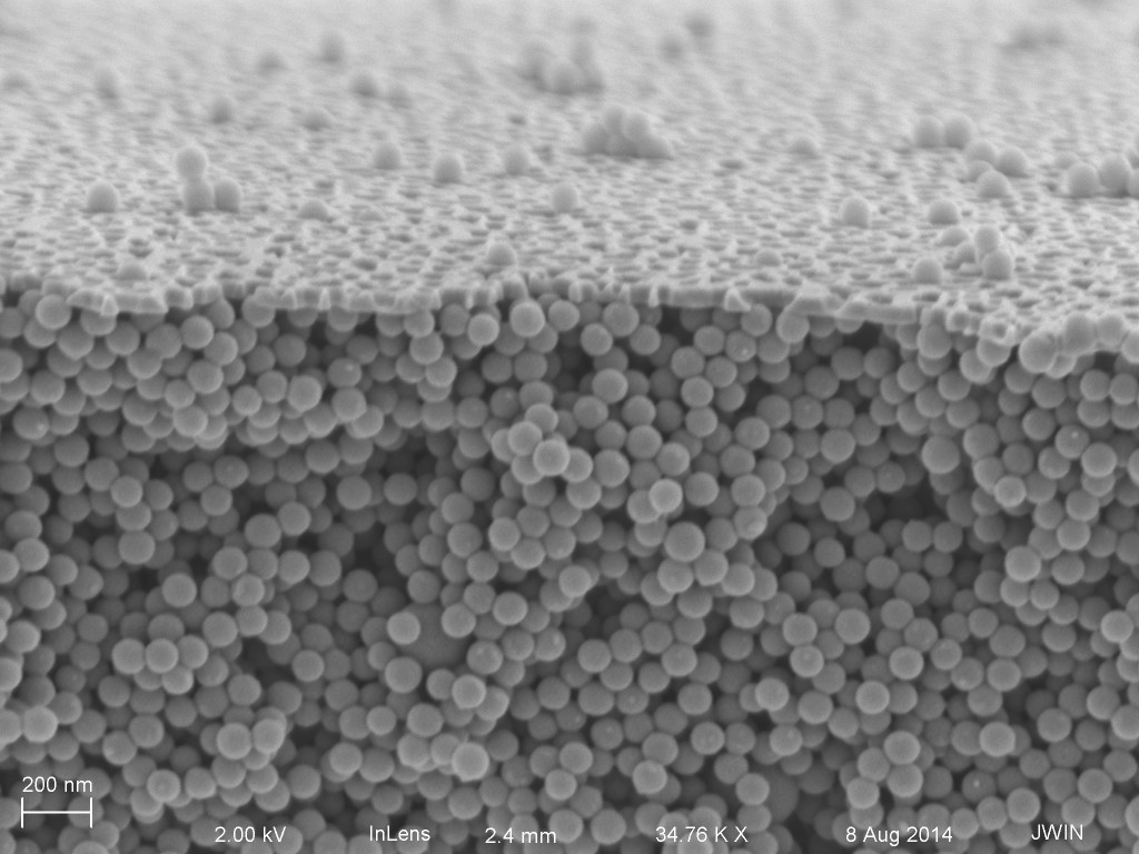
I haven’t imaged a 20 nm filter only yet. I’ll get to that at a later date. Below, though, I have SEMs from two filters used with 100 nm NPs. I have filters from two different concentrations 10^13 and 10^10, both FC.
First, 10^10:

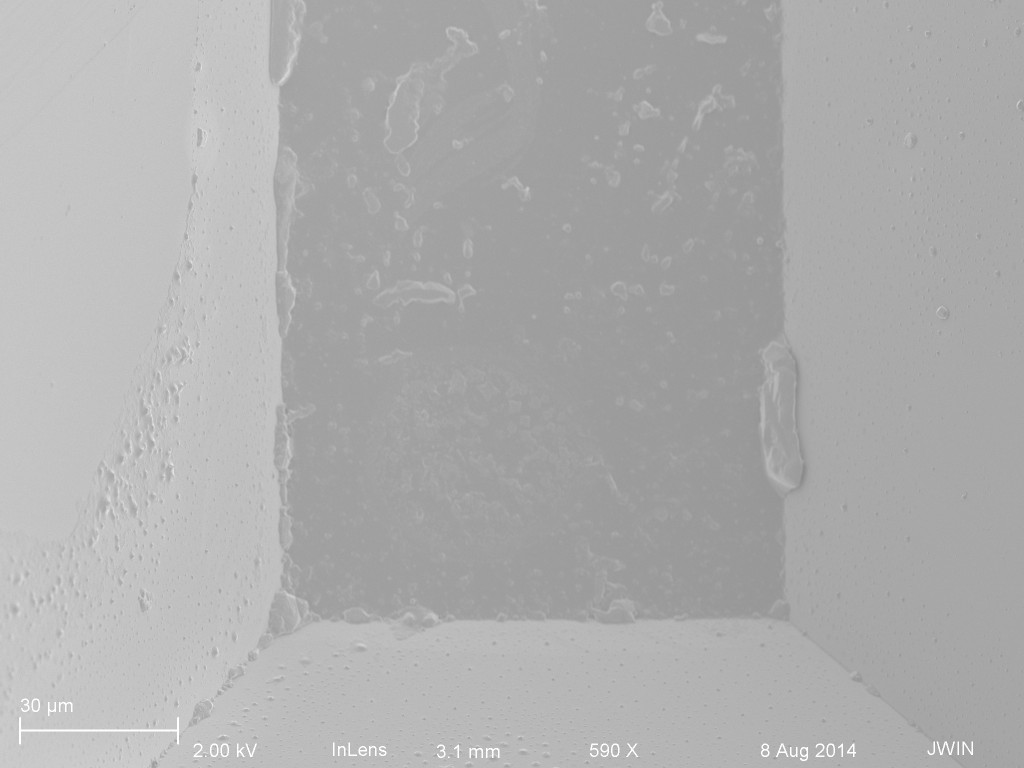

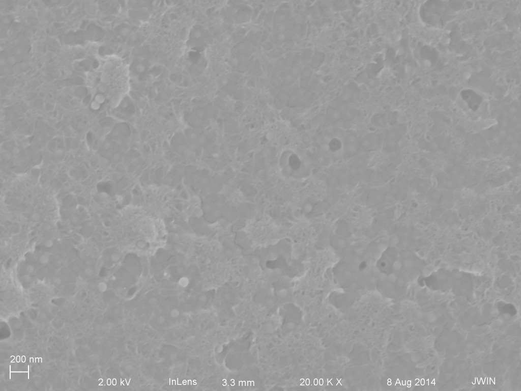
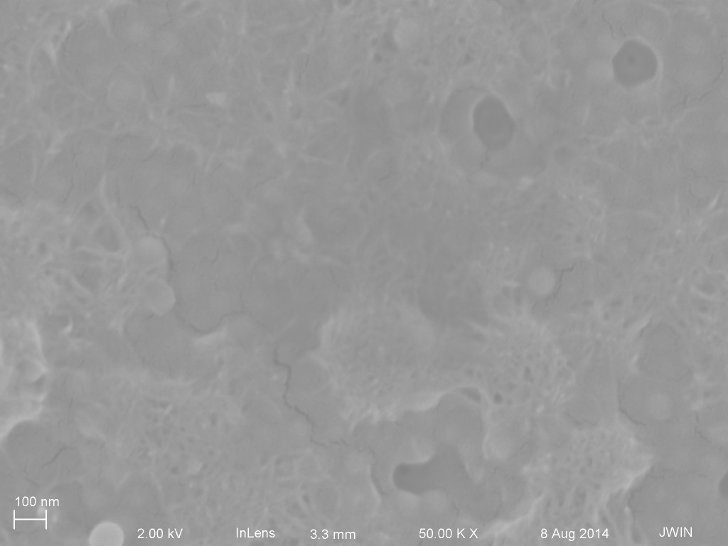

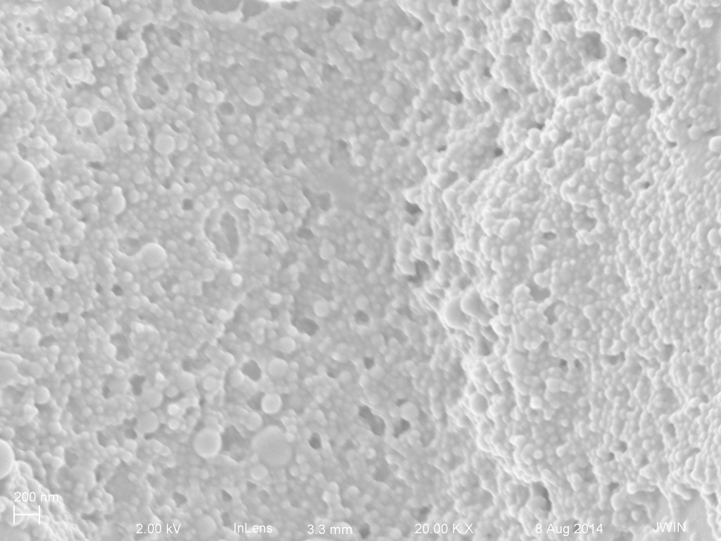
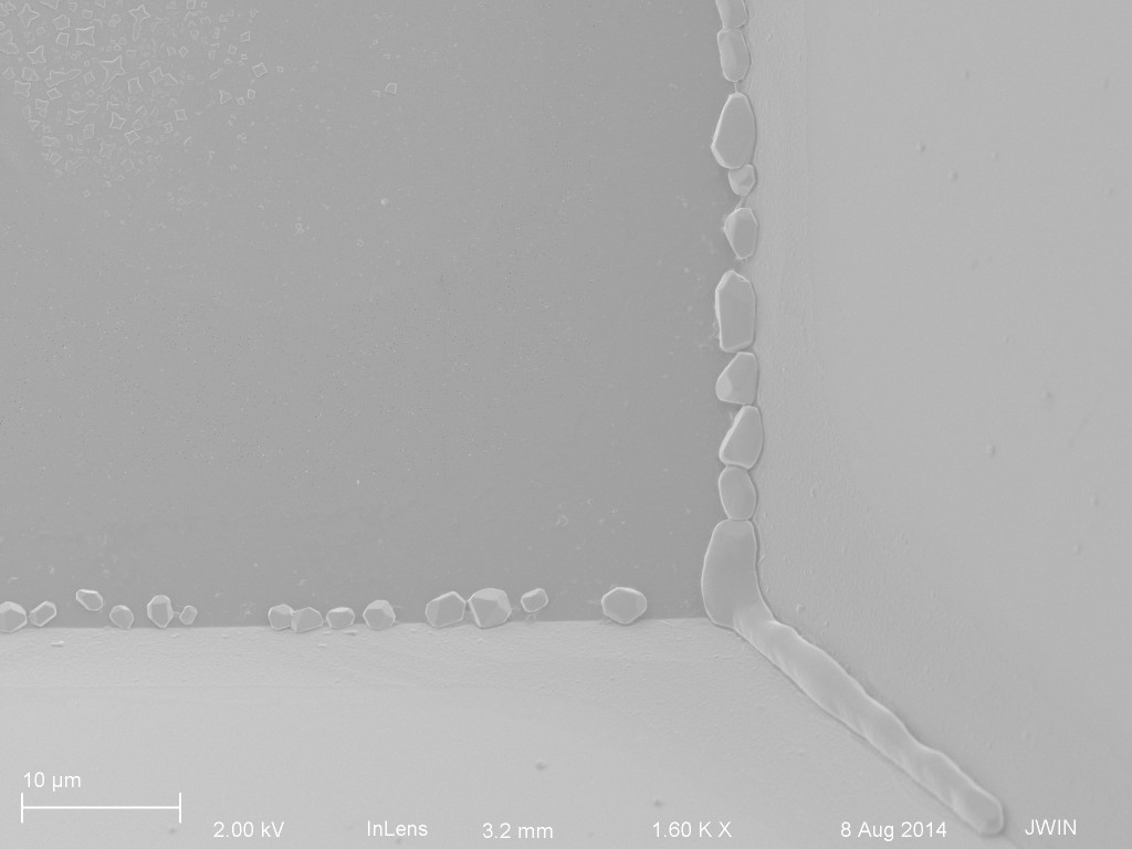
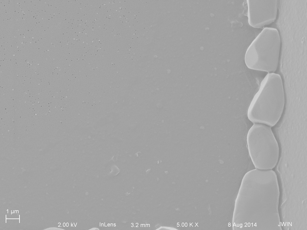
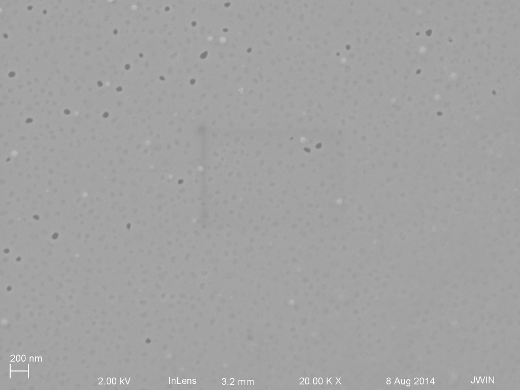
I know, I know. You’re underwhelmed. Well don’t worry, I save the best for last. 100 nm NPs at 10^13.


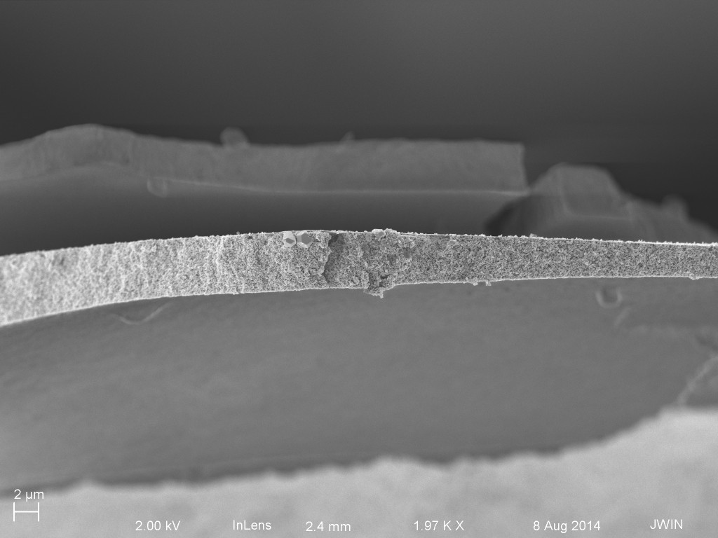
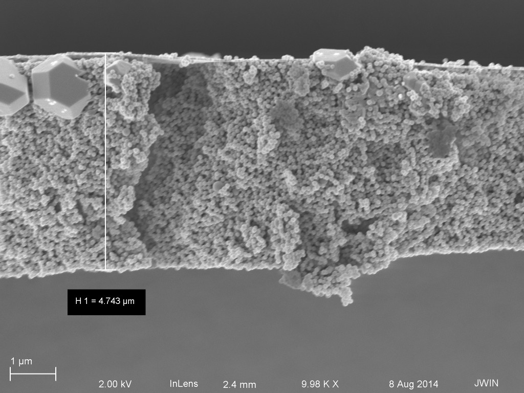
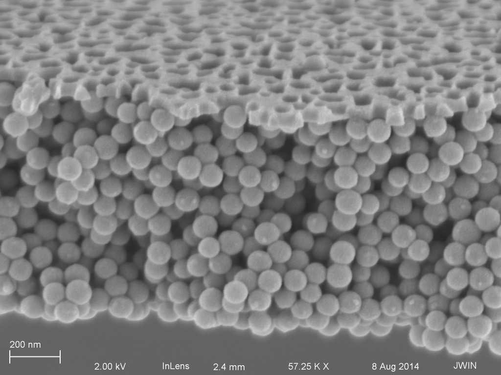
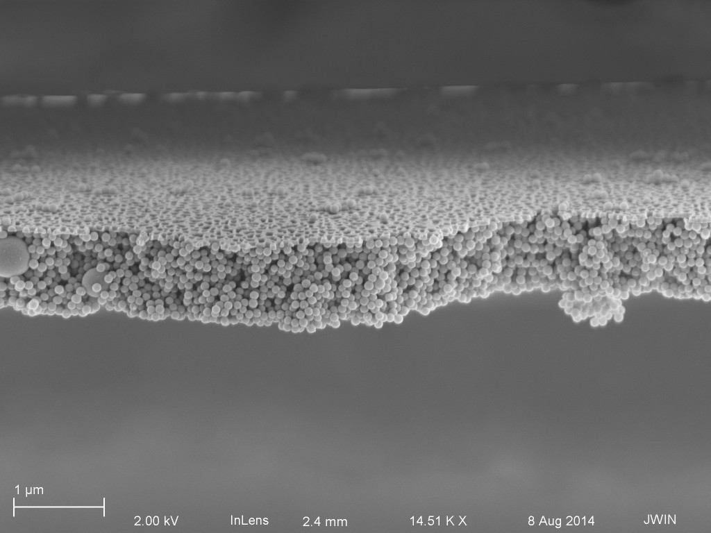
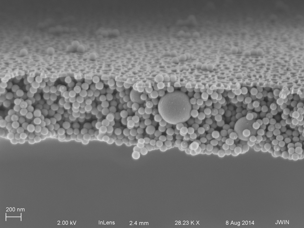
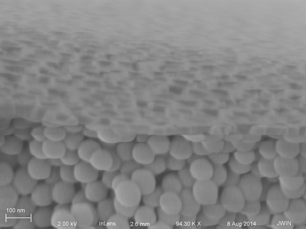
Pretty much everything about these SEMs make sense. It’s a shame that some 100 nm NPs ended up of the filtrate side. There’s a good chance that they got there during sample handling after they were removed from the SEPCON.