BBB Device v2-8
As the device animation shows, the layout of the chip has changed. The incorporation of through-vias in the bulk silicon allows me to eliminate a gasket wrapping around the filter, which was a large source of leaks. I used ozone bonding for 8 minutes for each layer to join the device together. I initially taped some aluminum foil electrode pads to the device to get better access for TEER measurements (using autoclave tape), but the tape didn’t hold up too well under pressure. Getting dollhouse tape to make a permanent bus on one side of the device will make the TEER recordings easier.
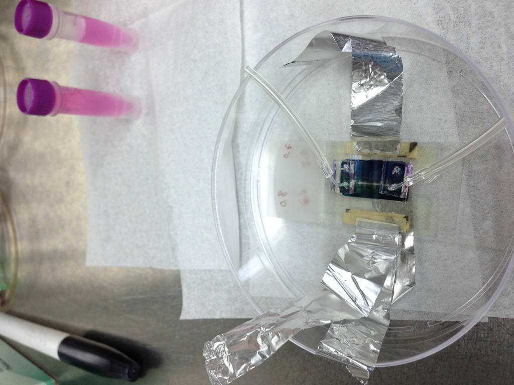
You can also see some curved capillaries being inserted into the device. These are fabricated by heating up the glass capillaries with a “wind-resistant” lighter and waiting until the glass droops, forming a right angle.

I seeded HUVEC cells from a confluent T-25 flask into the device. The cell density is low in the device when initially seeding; Yuchen suggested centrifuging the cells to get a higher density for seeding the device in the future. These cells have been contaminated by fungus, but should work well enough to demonstrate what is happening with the device.
Here’s a quick tomogram from the top channel (no cells) to the bottom channel of the membrane (seeded cells) at the end of day 1. These cells don’t appear to be resting on the membrane, rather, the bottom ITO electrode. The electrodes are transparent enough that we don’t see a hard boundary in the image, but if you stare at the image long enough, you may see two lighter and darker periodic regions. The measured TEER was 440 +/- 20 ohms, defining the background resistance of the device (EVOM2).
cool!