Electro-osmosis and Electrophoresis Discoloration
Electro-osmosis:
Yesterday I tried to study the electro-osmosis-like phenomenon that we were observing with the electrophoretic cell. All membranes again had pinholes. I set up the wells as before, but I would remove 50ul from the well which the negative electrode was attached. I turned on the voltage and waited until the water level came back up to the starting position in the negative well. I recorded the time and removed another 50ul and repeated the process. Now this isn’t a very precise method. It’s first hard to tell when the water level has exactly reached the top. There’s probably a good couple of minutes in which you could declare this, and I couldn’t sit around and watch a pot boil so to speak. At any rate, I think it gives us an idea on about the rate of water passage.
Here’s a chart of three trials I performed. In the first I used PBS alone, and attached the positive electrode near the membrane side. The second was also only PBS, but the negative electrode was near the membrane side. The last was performed using Rhodamine, and the positive electrode was near the membrane.

The Rhodamine sample seemed to slow down (may have been in my head too) and the retentate well began to lose all of it’s color. Something is deactivating the dye or forcing it all to stick on the membrane. The slits were once again bright red.
Discoloration:
In the previous electrophoresis post I showed that a membrane was discolored in 10min at 15V (5mA) when used to “separated” 1um beads. We weren’t sure if this was due to the beads or due to the electrode configuration. The beads were in contact with the membrane side of the chip, and since they are negatively charged, the negative electrode was in the same well. In all other experiments positively charged species were used, meaning the positive electrode was adjacent to the membrane side of the chip.
Yesterday I ran two experiments with PBS only on both sides to test electro-osmostic flow. In one experiment the positive electrode was adjacent to the membrane and in the other the negative electrode was adjacent to the membrane. Both experiments were run > 20min at 15V (5mA), and neither discolored the membrane. I then set up the same experiment as before with the beads, and again achieved discoloration. So I’d say that the beads are necessary to achieve this discoloration, although I’m not sure how they are involved. The beads are 1um polystyrene particles terminated in COOH.

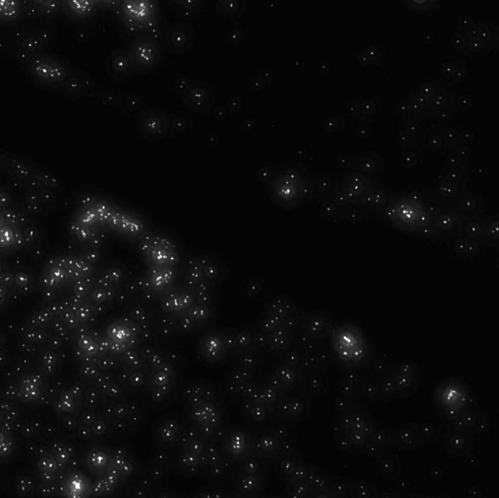
Dave and I looked at the discolored chip under Brian’s reflectance scope. We saw what appeared to be many tiny spherical spots of discolored membrane at the interfaces between discolored and non-discolored macroscopic fronts.
This image is focused on the front between discolored (silver) and non-discolored (blue) membrane. The two large white spots are pinholes.
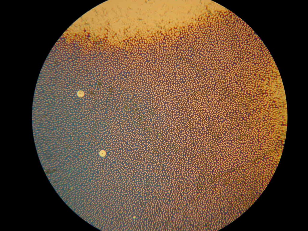
Karl was skeptical that the spots were caused by the beads, since this membrane was one of the ones with the pentane contamination. He went and discolored one of these membranes by the usual means, finding that it only lasted 14 hrs. He took an image and found similar spots.
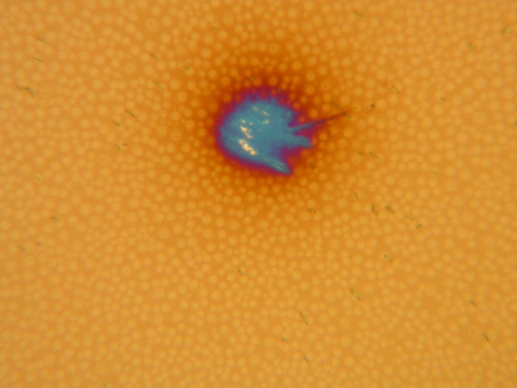
This makes sense because in my fluorescence images I never noticed that strong of a monolayer with the beads left on the surface. Of course, fluorescence could have been quenched, but it seems that the spots are not due to the beads. However, the beads are somehow contributing to the quicker discoloration.