Variation of TEER with finite area membrane
In my previous post, I mentioned the effects of varying electrode geometry on the TEER value measured from COMSOL simulations. I had assumed that membrane has uniform porosity i.e. 100% active area, which is the case with the commercial polymer membranes. pncSi and analogs, however, have only a a finite section of its total area porous; the newly developed flow chip has 2×0.7= 1.4 mm2 as the active area, with total area being~30 mm2. Due to this design constraint, it is necessary to understand the behavior of resistance drop across the membrane as the active area changes.
I modeled a cylindrical geometry with planar electrodes, which are of the same size as that of the membrane area. I then changed the amount of active area (keeping total membrane area and electrode area constant), and ran my DC simulations. I performed this iteration for three different values of total membrane area. The results are as follows
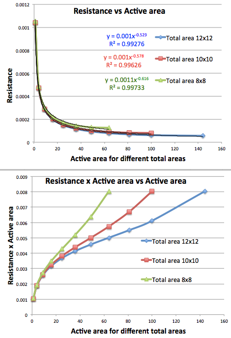
The resistance decreases as active area increases. The product of resistance and active area plotted against the active area, however, is not a straight line. It has a bit funny shape, upward concave in the beginning and almost a straight line near the end. Instead of dealing with absolute values of active area, I decided to normalize them with respect to the total area. After doing this normalization, the graphs for resistance and RxA for different cases overlap on the top of each other respectively. We can think of it as n=3. The graphs look like this.

As we can see from the above graph, the behavior of RxA vs ratio can be interpreted as another biphasic behavior. The region marked in dashed circle is the region where the ratio is low, i.e. barely any active area, so highly non linear behavior. As the ratio increases, the active area also increases pushing the system more towards the linear Ohmic model, as seen in solid circle. Just as you suggested today, we can devise a “formula” scheme that will tell us after what ratios, we can apply Ohm’s law. A good check is the fact that, all three curves meet at a single point when ratio = 1, implying that system is completely Ohmic at this point.
Thus we can conclude that the normalization procedure of multiplying resistance with the area is not going to help when dealing with a finite active area membrane, like pncSi. As a matter of fact, most of our materials have less than 10% area active, indicating that the system will be very non-linear and extremely sensitive even to minor changes in the area. An alternate way to beat this this, would be to construct electrodes of equivalent shape as that of the active area.