Towards integrating NSL membranes into PDMS devices
This post offers an update on membrane fabrication through nanosphere lithography (NSL), describing in more detail the releasing step as well as the membrane integration into PDMS devices.
Membrane lift-off is achieved by dissolving a ZnO film underneath the membrane. After fabrication the sample is immersed in 1M HCl solution. The figure below shows a comparison (top view picture and schematic x-section) of a representative sample before and after the releasing step. Once the ZnO has been completely dissolved the sample appears blue-ish due to the TEOS characteristic color against a Si background. The membranes rests on the original substrate from which it will be bonded to PDMS in subsequent steps.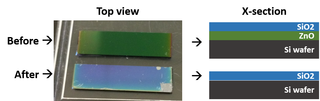
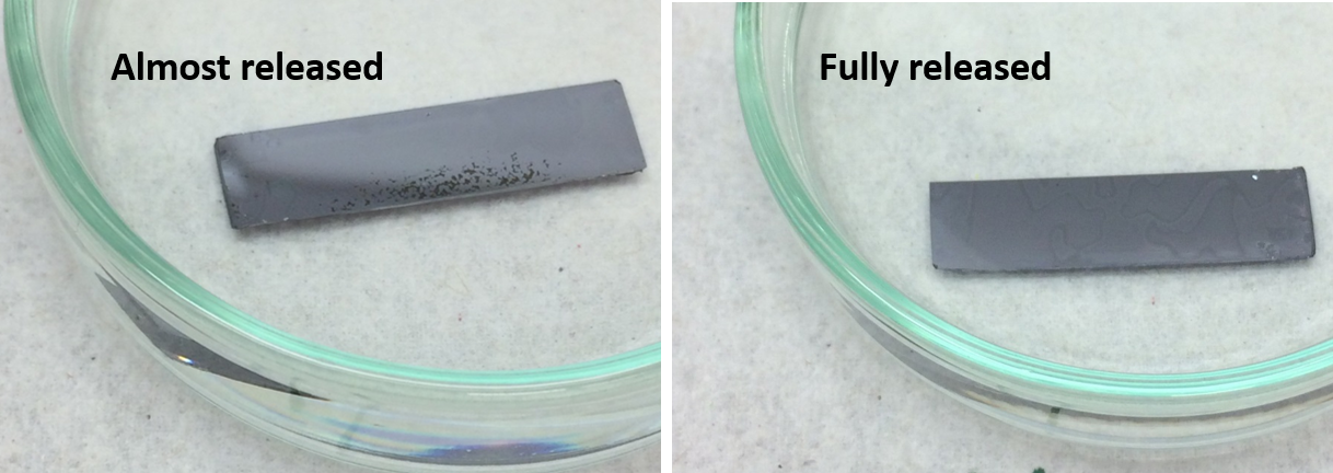
The figure below shows a comparison of a sample immersed in the HCl solution. The left panel shows the membrane almost released, the dark green (black?) spots are the leftover ZnO the rest of the membrane looks transparent because it is transparent.
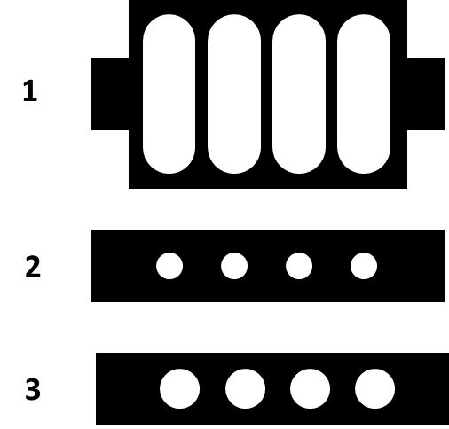
As it turns out, an ozone treated PDMS gasket bonds to the SU-8-SiO2 membrane. We started integrating the membrane into a simple 3 layer PDMS device to run permeability tests. Unfortunately or as usual, it can not be that simple. All membranes break while manually retrieving the gasket/membrane from the Si wafer. We have been sing the design below, courtesy of Henry, for maximum support and yield. I will keep trying other designs and handling methods to preserve the membrane.
Now, some pictures from a few samples. The picture below was taken from a sample with pores patterned from 300 nm beads, the picture show one of the 100×100 um windows. The left upper part is the Si wafer on which the membrane is resting, the right lower part is the membrane free-standing.

The picture below shows a membrane with pores patterned from 300 nm beads that have been reduced in size by an oxygen plasma to approximately half their original size.

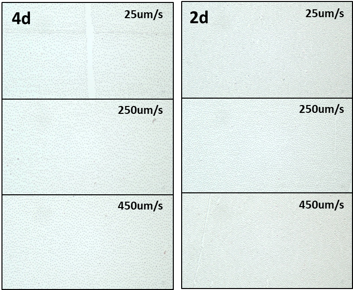
Finally, we have more control over controlling the spacing of the beads while keeping good arrangement. By arrangement I refer to minimum doublets (or aggregated beads) whit less than random positioning. Below is a comparison of samples transferred at different speeds, all should have an interparticle distance of 4 or 2 diameters. The comparison shows the effect of speed and how is related to interparticle distance.
We will continue to improve this fabrication process, focusing on the membrane integration into working PDMS devices. Any suggestions will be greatly appreciated. We are also in the process of elaborating a calibration curve that relates bead size, etching time, and final pore size.