BBB Device Design (updated)
The goal of the blood brain barrier device is to co-culture cells in a closed system, with the apical chamber under flow conditions, while still being able to access either chamber for media changes or to introduce new solutions. Electrodes to measure TEER will need to be included in future design iterations.
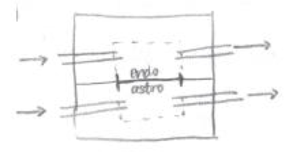
There are two possible configurations for the apical and basal layers. If both layers were to have capillary tubes inserted on the side, the same mold could be used for each layer (figure below, top). If the apical layer were to have the capillary tubes inserted on top, then a separate mold would have to be used for each layer (figure below, bottom). The benefit to having both sets of tubing enter from the side is that it allows for better imaging of the membrane and provides a cleaner, aesthetic look. Also, when culturing in the basal well, the device will need to be turned upside down for initial cell adhesion – having tubing coming out from the top will make it harder to balance the device. The challenge to having the capillary tubes on the side will be a clean insertion; this is why the tubing is currently on the top of devices like the Barrett chamber.
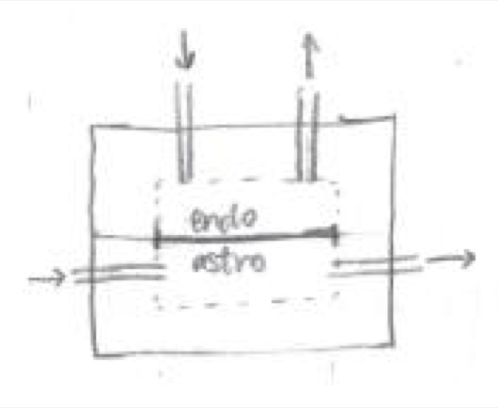
Assuming that both layers are the same, the dimension of each would be 20 mm x 11 mm x 2 mm, with a capillary tube (OD: 1 mm) inserted 0.5 mm above the bottom of the short side face. If the apical layer has capillary tubes inserted on the top face, they would be offset 0.3 mm from the side edge.
The chip itself is 20 mm x 11 mm, and the membrane is 10 mm x 0.5 mm x 300 um. The chip would be bonded onto the PDMS on the outer 1.5 mm, leaving 3.5 mm of the solid chip as a barrier to flow introduction (shaded portion on the figure below). I left this additional barrier because I was concerned that when flow was initially introduced, if the tube opening was too close to the cells, it could knock a few cells off the membrane or more greatly affect the cells near the opening. By having this barrier, the flow can be introduced slightly offset from the cells on the membrane, minimizing impact.

As a result, because the PDMS will be bonded to some of the chip edge and not all of it, the chamber will be slightly smaller. The dimensions for the chamber are 17 mm x 10 mm x 1.7 mm. Below are cross sections for both configurations, with the capillary tubes parallel to the membrane (top figure) and capillary tubes above the membrane (bottom figure); the membrane location was raised to give an idea where it would be. In the parallel configuration, a 1 mm support of PDMS was given below the capillary tube and 0.2 mm above. This gives a little bit of additional room when inserting the capillary tube, in case it was inserted spot on. I am a little concerned that the 0.3 mm of PDMS as the “roof” of the chamber may be too heavy and collapse, but this will be determined once the layer is made


Incorporating all components, the total dimension of the device would be 20 mm x 11 mm x 4 mm.